The hydraulic cylinder can realize the lateral parting or core pulling of the injection mold. Its movement is smooth, flexible and simple. Not limited by mold opening time and ejection time.
How to design a reliable hydraulic cylinder mechanism? In addition to the theoretical knowledge of the cylinder, these 8 points should also be considered in the design.
8 main points.
1. How to fix the hydraulic cylinder?
2. How to design the connection between hydraulic cylinder and plate?
3. How to install the hydraulic cylinder connector?
4. How to limited the rotation of the hydraulic cylinder?
5. Should the oil cylinder be designed with protection devices?
6. How to balance the ejection and reset of the oil circuit?
7. How to design the inductive switch?
8. Other matters needing attention.
In response to the above 8 points, we will discuss each one separately.
01. Fixing method of hydraulic cylinder.
There are two common ways of fixing hydraulic cylinders:
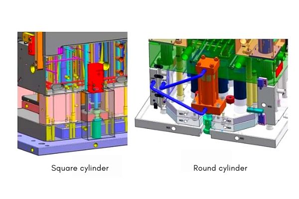
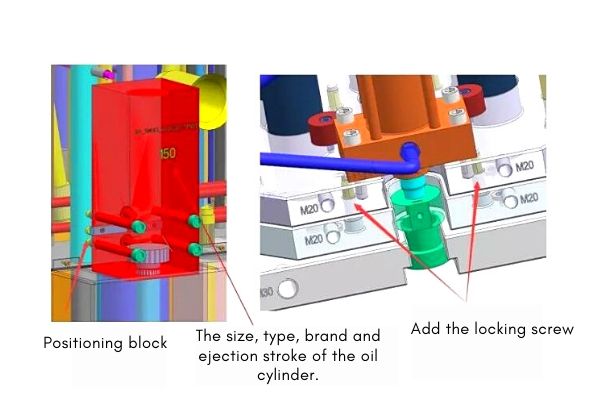
1. Square oil cylinder fixed on B plate. The cylinder should be positioned on the B plate.
2. Round cylinder fixed on the ejector plate. It should be noted that the ejector plate locking screw needs to be added next to the cylinder. This position is heavily stressed to prevent tension deformation.
In addition, it needs to be marked on the cylinder. Indicate the cylinder size, model, brand, and ejection stroke. This is to facilitate verification.
02. Design of the connection between the hydraulic cylinder and the mold plate.
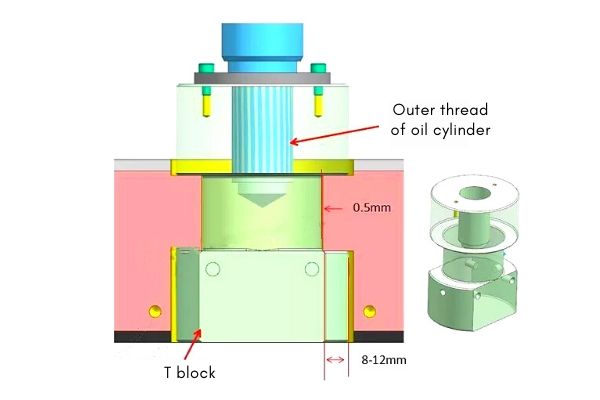
The hydraulic cylinder is connected with the plate design round T block. And the U-shaped groove is designed on the mold plate to facilitate processing and installation. The size of the mating surface is 8-12 mm, and the other positions are 0.5 mm away from the clearance height. There are two kinds of cylinder joints: internal thread and external thread. The joint of the internal thread can be directly screwed behind the T block.
Note:
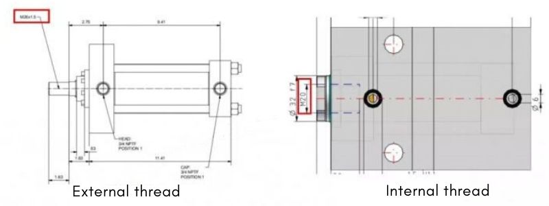
The thread size and spacing of the connector are subject to the 2D instructions provided by the supplier. In particular, it is easy to make mistakes if the thread spacing is not read.
03. Install the hydraulic cylinder connector.
There are two kinds of oil cylinder joints: internal thread and external thread. The joint of the internal thread locks the screw directly after the T block. The external thread needs to tap the T block.
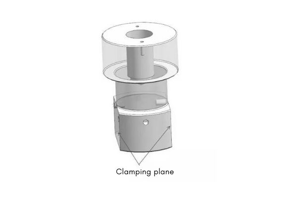
The T block is round and not easy to hold. It is necessary to cut 2 planes to twist the screws, this is the key.
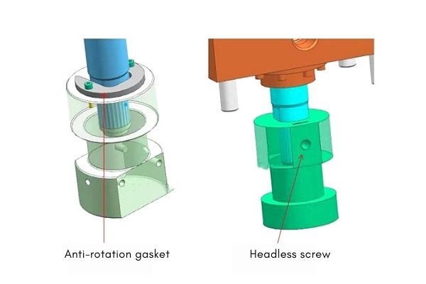
04. The rotation limit of the cylinder.
Why must the cylinder limit rotation? We can understand it this way. The moving piston in the cylinder is not restricted. During repeated overstroke, it may rotate, causing loose screws and potential safety hazards.
There are usually two design methods:
1. Make anti-rotation gasket.
2. Install headless screws.
The first choice 1, it is safer and more reliable.
05. Design protection device for the oil cylinder.
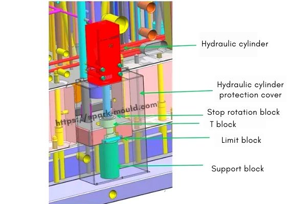
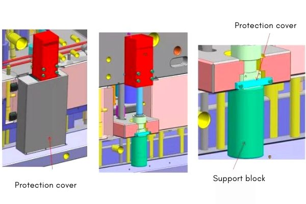
1.Oil cylinder protective cover (pictured). Large car molds are all set. Small molds are based on customer requirements, and some even cover all cylinders. The mold from playing a protective role during hanging, installation or transportation. Usually made of iron sheet.
2.Set the limit block. Prevent the locking screw of the fixed cylinder from loosening and the cylinder running outward. And it is convenient to disassemble and assemble the oil cylinder.
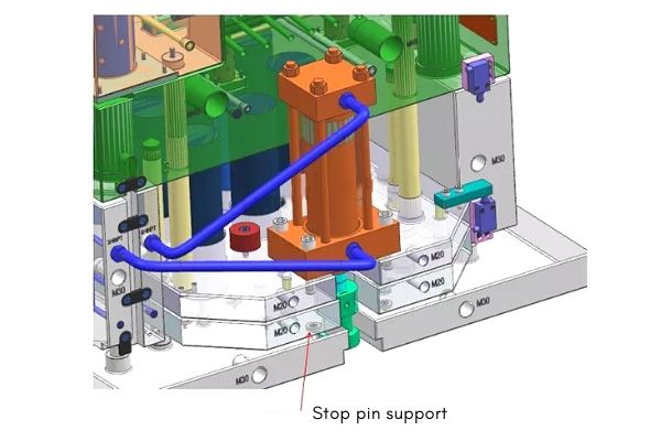
3.The support block is mainly provided to counteract the stamping of the reset of the oil cylinder and prevent the stamping deformation. Another method is to add stop pin support under the cylinder.
06. The oil circuit design balances ejection and reset.
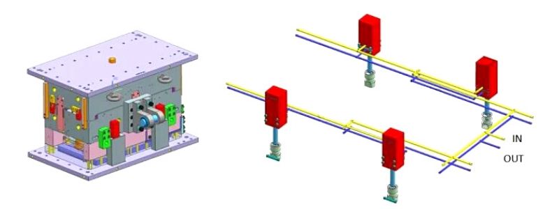
The purpose of the oil balance is to ensure the ejection balance. The length of the oil circuit should be as long as possible. If not, the difference should not exceed 50 mm. The oil circuit is designed to be open to facilitate the discharge of iron filings. Prevent iron filings from entering the cylinder and affecting work. The oil line pressure plug needs to be make thread, and it cannot be copper pressure plug. When the oil pressure is large, the copper plug can easily loosen and leak oil.
The following are several common oil circuit balance design schemes.
1.4 oil cylinders are ejected, suitable for molds with a size of 1500 mm or more. The oil circuit is designed on the B plate, and the oil inlet and outlet are designed on the non-operation side.
2. Two hydraulic cylinders are ejected, and the oil path is set on spacer block. The oil inlet and outlet are designed on the non-operation side.
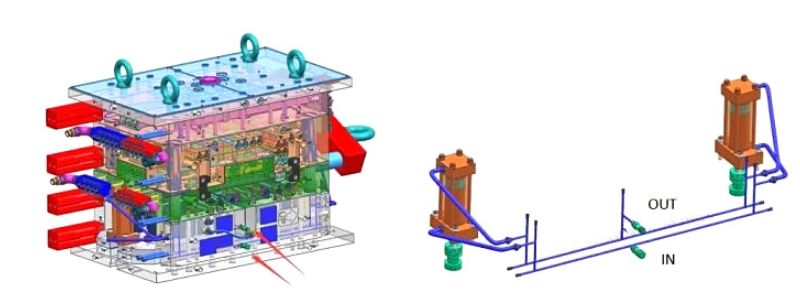
3. Two oil cylinders are ejected, and the oil path is set on spacer block. The oil inlet and outlet are designed on the sky side.
07. How to design the oil cylinder sensor switch.
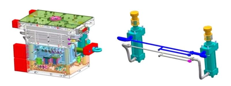
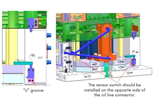
Sensor switches are required for cylinder ejection and reset. One set on each side of the large mold.
The sensor switch is mounted on an insert with adjustable distance. The U-shaped groove can be achieved by fixing the screws of the insert. In addition, it should be noted that the induction switch should be installed on the opposite side of the oil circuit connector to avoid interference with the oil circuit when it is ejected.
08. Other matters needing attention.
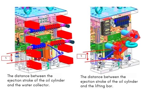
1. The ejection stroke of the oil cylinder cannot interfere with the water collector, check the ejection distance S.
2. The ejection stroke of the cylinder can not interfere with the lifting block, check the ejection distance S. When it is unavoidable, it needs to be disassembled after the injection molding machine is installed and prompted on the nameplate of the mold installation.
