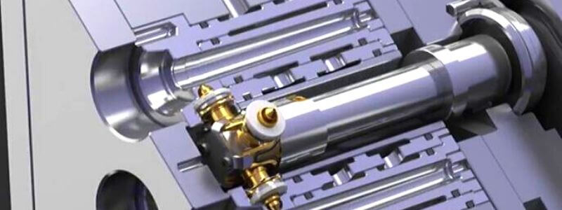
What is hot runner mold ?
Use the method of heating or insulating the runner. To keep the plastic from the injection molding machine nozzle to the cavity gate molten. In each injection cycle, only the plastic parts are ejected and have not runner scrap.
Foreword
Hot runner molds have many advantages. But its cost is also expensive. Therefore, we should be more cautious in the mold design and manufacturing process. Avoiding errors is the best cost savings.
There have 10 error points in the design. This will help, get it quickly.
1.The design was verified by mold flow analysis.
The molten material is molded into the respective cavities and reaches a pressure equilibrium state. The number of hot runner gates is typically a multiple of 2 or 3. Then determine the location of the gate and the number of nozzles. In order to make the quality of the product meet the requirements of customers.
2.Correct selection of nozzles for hot runners.
There are many nozzle types in the hot runner. Type selection is based on the actual conditions of the plastic parts and molds.
Cylindrical nozzle
The cost is lower. Feed directly on the surface of the product. Suitable for plastic parts with textured surfaces.
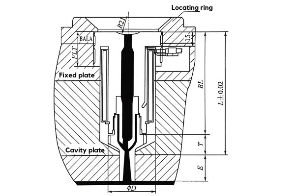
Open type
When the plastic parts are engineering plastic parts. Open nozzles should be used. Prevent nozzle clogging.
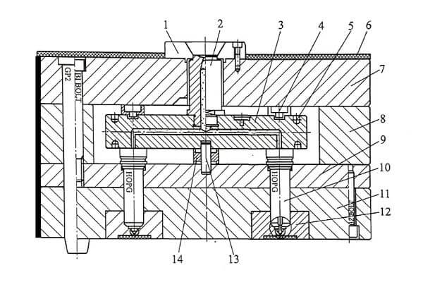
| 1.Loacting ring | 2.Main hot nozzle | 3. Hot manifold |
| 4. Insulation ring | 5. Heater | 6. High temp insulation sheet |
| 7. Panel | 8. Support plate | 9. Support pad |
| 10. Secondary hot nozzle | 11. Fixed A plate | 12. Fixed mold insert |
| 13. Loacting pin |
Needle valve or point
This type of hot runner system has an additional cylinder mechanism. Under the action of the cylinder, the valve needle is lifted up during injection. Seal the glue port at the end of the filling. It can effectively prevent flow marks.
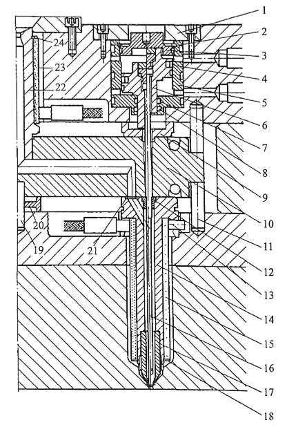
Graphic
| 1. Cylinder gland | 2. Hole circlip | 3. Upper cover |
| 4. OE seal | 5. Cylinder block | 6. Piston |
| 7. O-ring seal | 8. Guide belt | 9. Riser Pad |
| 10. Split runner | 11. Manifold locate pin | 12. Valve guide bush |
| 13. Nozzle locating pin | 14. Nozzle body | 15. Core heater |
| 16. Valve gate | 17. Nozzle head | 18. Shaft circlip |
| 19. Center locate pin | 20. Center support pad | 21. Runner seal |
| 22. Heating type main nozzle | 23. Main nozzle heater | 24. Shaft circlip |
3.The hot manifold is not well insulated.
The hot runner system is contact with the mold plate in a large area and requires a good thermal insulation effect. The insulation of the hot runner plates, nozzles and mold plate is mostly insulated by air. The structural parts should reduce the contact area with the plate. And there must be enough space.
As structure A show:
If the hot runner plate is designed as a whole with the pressure ring. It will make the hot runner heat insulation effect worse and cost increase.
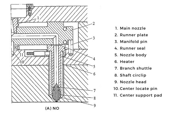
As structure B show:
The nozzles size of the nozzle is easy to adjust.Set enough cooling waterway near the nozzle. Avoid hot runner near gate halo.
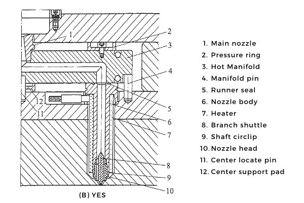
4.The runner of the runner plate has a dead angle.
If there is a dead angle in the runner. The will cause residual material to accumulate in the runner. There will be chromatic aberration in the plastic parts.
5.The nozzle of the hot runner leaks or clogs.
The hot runner nozzle will elongate due to the expansion dimension after heating. So in the design to calculate the expansion size of the nozzle. The size of the elongation after the nozzle is heated is processed. Otherwise it will damage the cavity and the hot runner. The tolerances required for the assembly are to be marked in the assembly drawing.
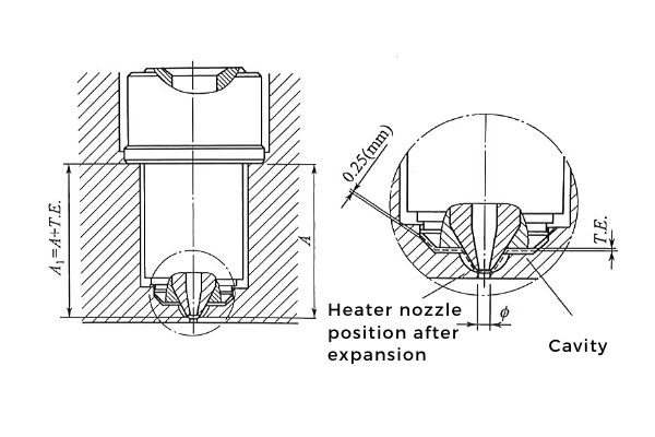
6.The center of the nozzle should be aligned with the center hole of the cavity.
The hot runner plate temperature is 200 °C. The cavity temperature is 60 °C. There is a difference in thermal expansion between the two.
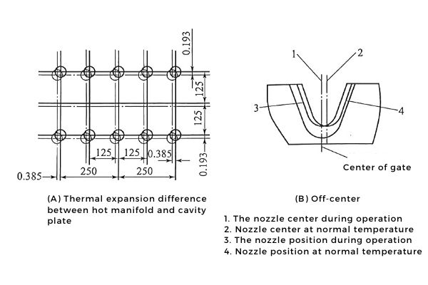
As shown in Figure A:
There must be enough space between the nozzle and the template. Correct the position of the hot runner touching the mouth. The correction amount is the amount of thermal expansion of the flow path plate. Ensure that the center of the nozzle hole and the center of the gate hole do not deviate.
As shown in Figure B:
The nozzle is made of high elasticity steel or high tension nickel bronze or beryllium bronze.
7.Hot runner plate and cavity plate fixing error
No.1
A screw structure cannot be used between the two.
As follows. If it is fixed directly with screws. The direction of thermal expansion of the runner plate is limited. Will cause the runner plate to tilt up.
As show picture B. Use stepped screws. L1 is 0.05 mm higher than L. The runner plate has enough space to expand and contract.
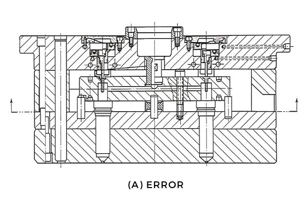
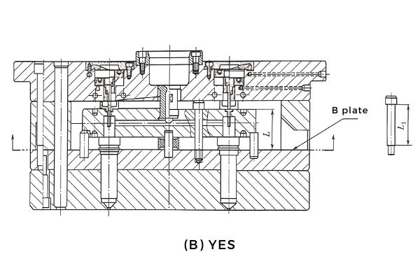
No.2
As show blow. The locating sleeve is used to support the end face of the bolt. This solves the problem of the bending of the locating bolt.
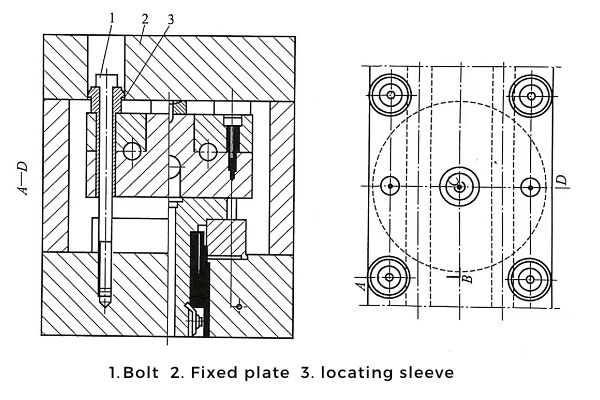
8.Hot runner design should consider plastic properties.
The injection mold adopts a hot runner structure and is selected according to the properties of the plastic. See Table for details.
| Performance | Plastic |
|---|---|
| Good | PP , PZ , ICP,TPE |
| Qualified | ABS , SAN ,PET, PBT, POM , PA , PPE , PPO , PPS , PC/ABS , PC/PEBT |
| Poor | PC , PMMA , PEEK , PES , PEI , POM |
9.The runner hole of the hot runner plate has a rough surface.
The surface roughness of the runner holes is consistent with the surface of the cavity. Avoid rough runner holes as much as possible.
10.Hot runner electrical component design misunderstanding.
1) The hot runner system does not match the electrical power.
The electric power calculation is calculated in 1 kg mass corresponding to 1-1.2 kw. Currently, hot runner systems are standard or custom made. It has been supplied by the hot runner manufacturer.
2) Wires must come in and out of the top of the mold.
Prevent cooling water from wetting the wires. Caused a leakage accident.
3) The thermo couple is not installed correctly.
The flow plate and the 2-stage nozzle are separately temperature control. Minimize the temperature difference between the runner plate and the class 2 nozzle. Thermocouples are usually placed in the highest temperature areas. Between the runner and the hottest part of the heater.
4) Pay attention to the electric safety of hot runners.
The power cord should be fixed and protected from friction with the components. At the same time, used wax tube to protect the wires.
5) Hot runner components are not numbered accordingly.
Make sure the heater and power supply temperature control line correspond when wiring. The hot runner plate nozzle point and the cavity are numbered accordingly. The center feed is 1 and the rest is from the upper right. Numbered counterclockwise from the x-axis y-axis. As the picture shows.
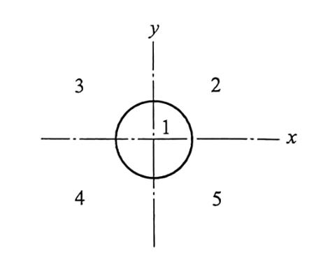
At the end
This is the basic 10 point suggestion. Maybe it will help you recall more details. If you still have questions, please feel free to contact us.
