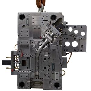
What is Side Core Pulling Mechanism?
When there are inner and outer holes or undercuts on the plastic part that are different from the mold opening direction. Plastic parts cannot be ejection. The molded side hole or the undercut part must be made into a movable movable core. And the movable core is taken out before the plastic part is pushed out. Then take out the plastic parts. The mechanism for accomplishing these actions is called a side core pulling mechanism.
Here are 7 design tips for the side core pulling mechanism.
1.How to ensure the processing technology of the side core pulling mechanism?
No.1
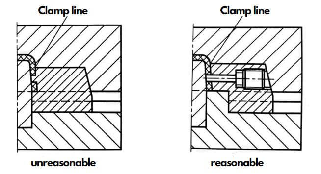
Slide insert should try to avoid the creating of Clamp line on the plastic parts. If it is inevitable, the position of the clamping line should be located where the plastic parts are not obvious. And the length of the clamping line is as short as possible. At the same time, the slide insert should adopt a combined structure. The molded part can be processed in combination with the cavity. To ensure that the clamp line is smooth and flat. As shown below:
No.2
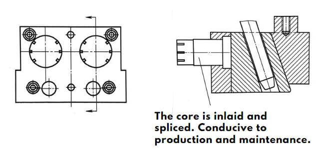
In addition, the slide insert and the slider should also be combined as much as possible. This facilitates the processing of lateral core pulling structure. As shown below:
2.How to ensure the strength and rigidity of the lateral core pulling structure?
Generally, the dimensions of the side core pulling mechanism are designed empirically. Simplified calculations are also possible. In order to ensure sufficient strength and rigidity, the following principles should be followed.
Largest structural size
The slide insert parts are of the largest size in sufficient space.
Structural Design Optimization (Here are 5 examples)
No.1
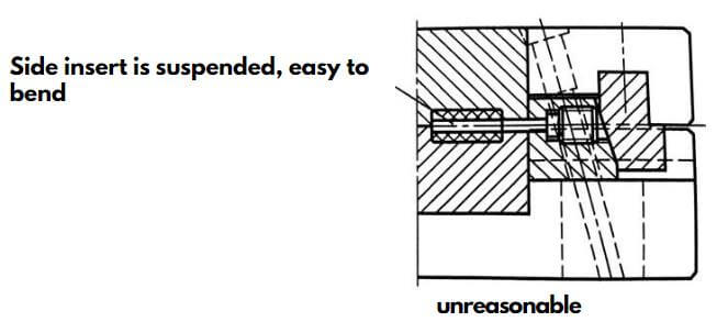
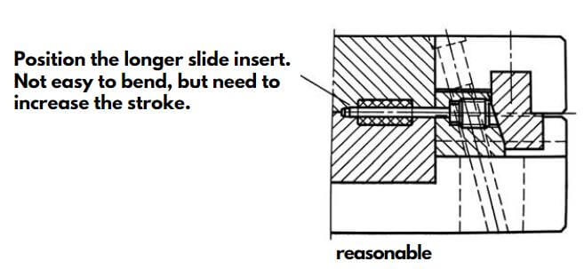
If the circular slide insert is long, the end should be positioned. This will avoid core bending. As show below:
No.2
Increase the section size and tilt angle of the cam. Prevent the inclined rod from link bar. As show below:
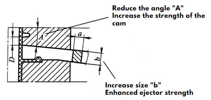
Within the allowable range of the plastic structure space “D”. Increase the section size “a” and “b” of the cam, especially the dimension “b”. At the same time, reduce the angle “A” on the premise of satisfying the slide insert distance.
No.3
Improve the structure of the wedge. Increase the strength of the assembly parts. AS show below:
.jpg)
.jpg)
.jpg)
.jpg)
No.4
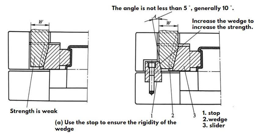
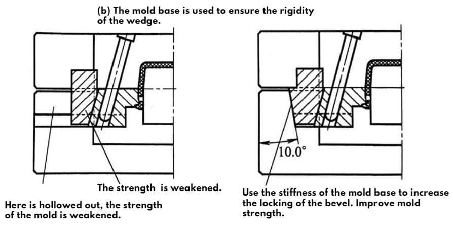
Improve the rigidity and locking strength of the wedge. As show below
No.5
Improve the assembly structure. Increase the size of the parts and increase the strength of the mold. As show below:
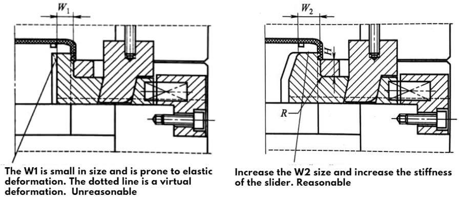
(a)In the figure, “W1” is small and easily deformed. (b) Improved component structure and increased component size “W2”. Helps to increase strength. You should also increase the fillet at “R” and reduce the size of the “H”. Avoid reducing deformation. “H” generally takes 8.0 ~ 10.0 mm.
3.How to ensure the safe and smooth movement of the sidecore pulling mechanism?
During the mold opening and closing process, the side core pulling mechanism does not interfere with other structures and components. And the sequence of motion is safe and reliable. Usually consider the following points.
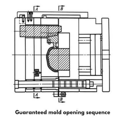
No.1
When using a fixed-mode slide insert, the mold opening sequence should be guaranteed. As shown below. When opening the mold, it should be first typed from A-A and then typed at B-B.
No.2
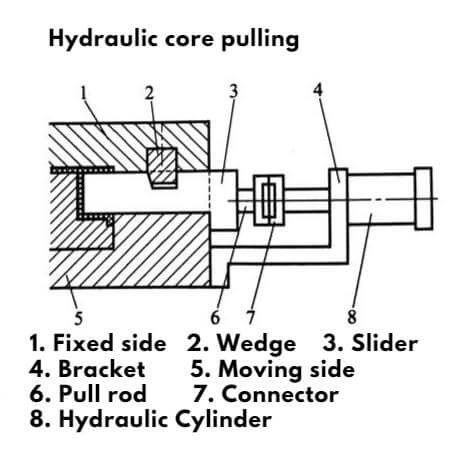
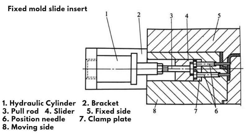
When using a hydraulic (air pressure) side core pulling mechanism. The parting and reset sequence of the slide core must be controlled. Otherwise the slide insert will be damaged. As show below:
Hydraulic core pulling
As show below. The cylinder is only activated when the wedge 2 leaves the slider. The side core pulling mechanism can be parting. Before clamping, the cylinder must first push the side core pulling mechanism to reset. After the mold is closed, the slider is locked by the wedge 2.
Fixed mold slide insert
As show below . The slide insert is passed through the cavity insert. Therefore, before the mold is opened, the hydraulic cylinder is opened to extract the slide insert. The lateral core pulling mechanism can be reset after clamping. The slider is locked by the cylinder pressure.
No.3
The side core pulling mechanism should prevent interference with the ejection mechanism when clamping the mold. When the projections of the side core pulling mechanism and the ejection mechanism in the mold opening direction coincide. It is necessary to first reset the ejector mechanism. Otherwise the two may interfere (commonly known as collision mode).
No.4
When the angle pin or the square dowel is long, the length of the guide pin should be increased.
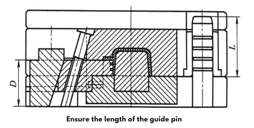
Length of guide pin L ≥ D+15mm
The purpose of lengthening the guide pin is to accurately position the fixed and movable molds. Avoid damage to the side core pulling mechanism during the mold clamping process.
4.How to ensure enough slider stroke to facilitate ejection of plastic parts?
No.1
The slider stroke must first ensure that the slide core is removed from the plastic part. Secondly, it is also convenient to take out the plastic parts from the mold.Slider stroke is taken from the side hole position or the lateral concave and convex depth plus 1~5 mm.
No.2
For medium and large molds, when the lateral core draw area is large. The slide core distance can be increased by 5-20 mm based on the lateral concave and convex depth.
No.3
The cam and the link bar are taken as the minimum value, and the other types are taken as large values.
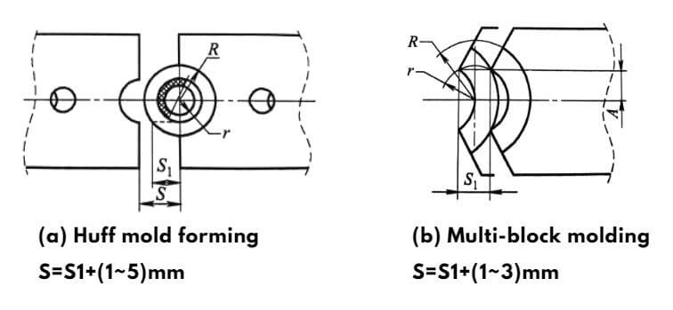
However, when a mold such as a coil bobbin is molded by a flap mold (also known as a Haf mold). The stroke cannot depend only on the depth of the undercut and on the radius of the undercut.
The calculation method of the stroke S is as shown in the figure.
5.How to ensure that the slider is stable and reliable and should have a sufficient service life?
No.1
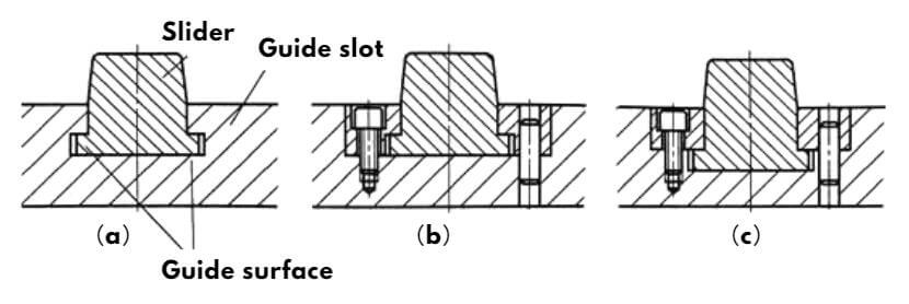
The side core pulling mechanism is guided by a T-shaped guide groove. as the picture shows.
No.2
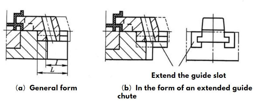
When the lateral core pulling mechanism completes the side splitting, the slider is preferably left in the guide chute. When the slide core distance is too long. The length remaining in the guide groove should not be less than 3/4 of the length of the slider. Otherwise, when the wedge pushes the slider to reset, the slider is easily deformed due to the torsion force. When the slide insert distance is too large, an extended guide groove can be used. As shown.
No.3
The sliding surface of the slider should have sufficient hardness and lubrication. In general, the lateral core pull assembly must be heat treated. Its hardness should reach above 40 HRC. The hardness of the sliding part should reach 52~56 HRC. The oil guiding groove should be made in the sliding part.
No.4
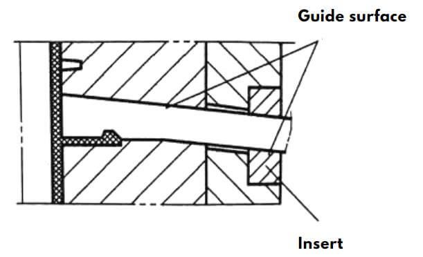
In the side core pulling mechanism of the cam link bar. The sliding surface cooperates with the hole wall of the inclined top swing rod. To reduce the wear of the sliding surface, the actual mating surface should not be too long. In order to increase the hardness of the sliding surface, the part should be made of high hardness inserts. As shown in Figure.
6.How to ensure the accurate positioning of the slider?
When the lateral core pulling mechanism terminates, the slide core stays in the corresponding position. Ensure a smooth reset when clamping. A reliable positioning device must be provided. However, the lateral core pulling mechanism of the cam type does not need to be provided with a positioning device. The figure below shows several common positioning structures for sliders.
Structure 1
Common use. However, due to the limitation of the built-in spring, the stroke is small.
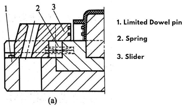
Structure 2
It is suitable for the side core pulling mechanism of the slider above the mold or the larger core distance. When the lateral core block is above, the spring force should be more than 1.5 times the weight of the slider.
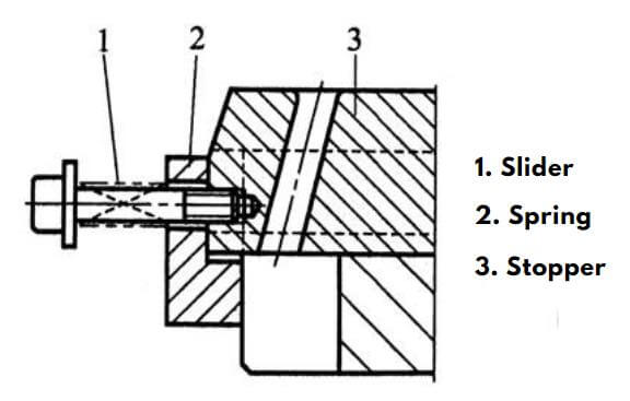
Structure 3
This mechanism has a poor positioning effect. Only applicable if the slider is on the side.
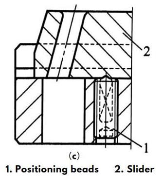
Structure 4
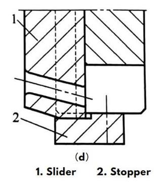
This structure is suitable for the slider located below the mold. Using its own weight rests on the slider stopper.
7.How to guarantee the power of the side core pulling mechanism?
The power of the slide core is guaranteed by the mechanical mechanism. Avoid the use of springs alone.
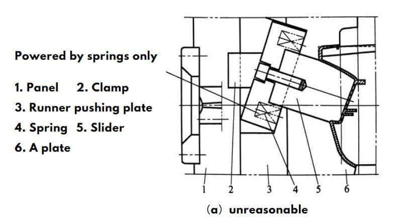
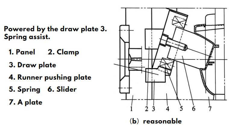
(a) The use of the spring alone to provide the opening power, the structure is unreasonable. (b) Mainly provided by the pull block “3”, the slider opening power is guaranteed. The structure is reasonable.
Conclusion
The side core pulling mechanism is an important mechanism in the injection mold. The seven design points presented in this article can solve most of the problems. A reasonable mold design can save the manufacturing cost of the mold. And improve the life of the mold.
If you have questions, you can contact us for technical support.
