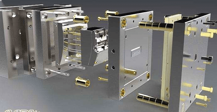
About Large-scale injection mold
In recent years, with the advancement of polymer technology, advanced manufacturing technology, computer-aided technology (CAD, CAM, and CAE) and other related technologies.Large-scale injection molds account for an increasing proportion of the entire mold output.Such as car bumpers, dashboards, TV housings, washing machine inner cylinders, TVs, air conditioning machine parts, tubs, barrels, turnover boxes and other large injection mold products.
Due to the high cost of large injection molds. Therefore, the requirement of design and manufacture must be a success. Avoid rework. It is not allowed to be scrapped due to improper design.
Large-scale injection mold design experience
In terms of design, manufacturing, and injection molding technology, large molds are basically the same as ordinary injection molds.But large models have many unique features. Such as strength design, pouring system design, structural design, processing methods.In the design process, if there are mistakes in these aspects. It can cause huge losses.

Large-scale mold strength and stiffness requirements
Large molds have large pressure, large cavity size, large deformation, and large core support distance.Structure must be designed to strengthen the knot solve these problems.For example, in the cavity, the edge of the core design stop cone positioning. The support column is designed on the bottom surface of the core.
Molded part design
Designing small molds for cavity insert and core insert.Often designed as a whole. This structure is simple and easy to process.For large molds, monolithic structures are generally not used. Instead, a modular cavity structure is used.The purpose is to save precious metals and reduce the amount of machining. Easy to grind, polish, and heat treat.
In general, the larger the mold, the more complex the molded parts.If a modular structure is adopted, its superiority will be greater.However, attention should be paid to the fact that, when using a modular structure, in addition to satisfying its rigid conditions, the form of its combination must also be carefully considered.


Gating system design
For large molds.Prior to determining the design of the mold structure, the product should be subjected to a mold flow analysis.Determine the location, quantity, form, etc. of the gate.In general. Large injection molds usually use hot runner gating systems. Thus the design of the hot runner and mold design should be combined.
Exhaust system design
From a certain point of view, the injection mold is also a conversion device.When the plastic melt enters the cavity, the air in the cavity is discharged. In fact the air inside the mold is not confined within the cavity.In particular, the three-plate injection mold structure cannot ignore the air existing in the gate and the runner.In addition, the resin in the molten state generates a slight amount of gas. As the amount of plastic increases, more gas is produced.

If the filling process, the gas can not be quickly discharged. Plastic parts have these defects.
- Bubble formation, silver, fogging, weld line on the surface of the article. Causes the surface contours to be unclear and mold filling dissatisfaction.
- In severe cases, scorch marks are produced on the surface of the product, resulting in the product being scrapped.
- Reduce the filling rate. Affects molding time and product quality.
- Formation of intermittent injections reduces production efficiency.
Therefore, the solution for the exhaust problem of large molds. In addition to the use of parting surface, core, putter and other clearance exhaust. Also need to set up a dedicated exhaust gap, design principles are as follows.
- Position of the exhaust gap Designed at the end of the plastic melt flow, or where the wall thickness of the product is weak. And away from the operator.
- Exhaust clearance size Depth should be easy to vent, no spillage of raw materials.The value is determined by the viscosity characteristics of the plastic melt.The continuation depth can be increased by 0.2~0.8mm. The width of the exhaust gap, according to the size of plastic parts, optional 5 ~ 25mm. In addition, 10 mm around the cavity can also be processed into a closed annular groove to the atmosphere. This exhaust is very good.
- Not only to consider the exhaust but also to consider the mold is the intake. If you open the mold gas can not enter the cavity. A vacuum will form between the plastic part and the cavity, causing the mold to fail to open.
Commonly used plastic exhaust groove depth
| Resin Name | Exhaust slot depth/mm | Resin Name | Exhaust slot depth/mm |
|---|---|---|---|
| PE | 0.02~0.04 | PA(Containing glass fibers) | 0.03~0.04 |
| PP | 0.02~0.04 | PA | 0.02~0.04 |
| PS | 0.02~0.04 | PC(Containing glass fibers) | 0.05~0.06 |
| ABS | 0.03~0.05 | PC | 0.05~0.08 |
| SAN | 0.03~0.05 | PBT(Containing glass fibers) | 0.03~0.05 |
| ASA | 0.03~0.05 | PBT | 0.03 |
| POM | 0.02~0.04 | PMMA | 0.04 |
| EVA | 0.02~0.04 | CAB | 0.02~0.04 |
